The electrons, in their passage through the conductors and semiconductors, produce a lot of heat, and they negatively affect the final performance of the circuit. The biggest obstacle is caused by the implementation of microelectronics, which does not get along very well with heat dissipation. In recent decades, the power density in electronic devices, has increased significantly. The tendency to reduce the size of the devices has increased thermal problems within electronic circuits. Therefore, temperature management in power devices remains an extremely critical factor. A review of techniques and methods to better manage the problems related to the thermal aspect of the system becomes essential.
Thermal analysis of electrical devices is an indispensable step to ensure stability to the system. And it’s more important with miniaturized and high-performance devices. Thermal analysis generally calculates the ranges of working conditions and the heat conduction between the parts. The designers study the hot air path to avoid air pockets trapped in the circuit. The heat can be dissipated both through forced convection by the fans and through natural convection. The functioning of the electronic energy transformation circuits depends on the calculations made by the designers. Thermal simulation is an excellent ally of designers. It helps them design prototypes without physically building the mechanical and electronic parts. The presence of small detail can have a great effect on the final circuit. Some solutions involve the use of fans and this must be considered by the designer.
High temperature: negative effects
The temperature changes the reliability and durability of the electrical and electronic components. A device malfunction is almost always caused by a thermal problem. The increase in temperatures in the circuits can cause premature aging of the equipment, while low temperatures can favor the formation of condensation with the risk of damaging the devices and with a risk of corrosion. Power and high temperature create an inseparable combination. In every system a small part of the power is transformed into unused heat (see figure 1). This is the case of power circuits, inverters, converters, choppers, power supplies, in which a high amount of heat is produced, especially if they have not been properly designed.
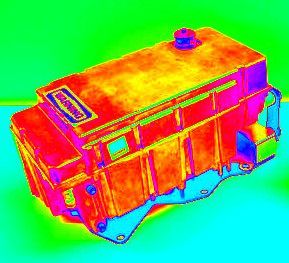
Figure 1: The heatmap developed by an inverter with IGBT
If the power devices are designed with excellent construction criteria, in compliance with regulations, following operating limits, using fast switching components and with low heat dissipation, the systems will work at lower temperatures with greater efficiency. One of the biggest problems of high temperature in electrical circuits is a reduction in efficiency. High temperatures are the enemy of integrated circuits and electronic components in general (see figure 2). High temperatures not only make the system work unstable, but also reduce the average life of the components, thus leading to their deterioration.
Summer is the critical time for power device overheating problems. Bad heat dissipation is generally caused by dust, fan problems and blockage of the air duct. The protection circuits lower the final performance or even stop the operations. The operating temperatures depend not only on the functioning of the electrical circuit but also on the place of use. The ideal situation would involve a cool and airy environment, but this is not often possible. A proper balance is needed between the internal and external temperature.
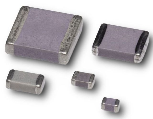
Figure 2: Smd ceramic capacitors for high temperature (up to 250°C)
Even if the performance of power devices is very high, the heat generated is always excessive. An example clarifies any doubt: suppose we are using a ten (10) kW inverter with a 98 percent efficiency. It is a device with an excellent yield. Two (2) percent of energy, equal to 200 W, is lost in unused heat and this thermal power represents a fairly high value. Even the temperature on the container of the device also affects the degree of efficiency. If it goes too high, the circuits must reduce their power. In some circumstances, it is not possible to use all available module power.
How to handle high temperatures
At the operational level, the user should perform simple maintenance on the devices, such as removing dust and cleaning the air duct, to ensure the normal operation of the equipment. Obviously, the system must be designed to heat as little as possible, focus therefore, should be on some precautions to be taken when designing the power devices.
Heat sinks
The first precaution to take is to adopt and implement a strategy to disperse the heat of the electrical and electronic circuits. The heat transfer efficiency of the heat sinks is linked to the thermal resistance between the heat sink and the ambient space. It measures the ability of a material to dissipate heat. A heat sink with a large surface area and a good air circulation (airflow), provide the best heat dissipation. For this purpose, suitable heat sinks must be installed in direct contact with the interested parties (figure 3).
An ideal heat sink material must have high thermal conductivity, low thermal expansion coefficient, low density, and low cost. The materials used are copper and aluminum: the former is used in cases where maximum efficiency in thermal transfer is required, with higher cost and greater specific weight; the latter is chosen for less demanding operating conditions. However, these days, a new science on thermal materials is being studied and in the near future, technology will help produce new materials with better properties and lower costs.
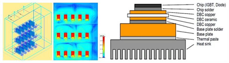
Figure 3: A simulation of a heat sink
The on/off of the metal-oxide-semiconductor field-effect transistor (Mosfet) inside a system is used to adjust the output power, so as to achieve the purpose of saving energy and adjusting speed. Cooling is critical to the performance and service life of a circuit. Today, there are double-side cooled power modules which deliver superior cooling performance for improved robustness to thermal cycling. The semiconductor dies are sandwiched between conventional Direct bonded copper (DBC) substrates, the substrates being directly cooled rather than through a conventional heat spreader, heat sink assembly.
Figure 4: A software can simulate the system
Designers must implement devices for efficient and reliable cooling of the enclosure that contains the circuit. If this is made with care and precision, it also acts as a heat sink. This way, devices can operate at maximum rated power, even with ambient temperatures up to 50° C. Many highly professional software allow you to simulate the entire system, made up of electrical, physical and hydraulic subsystems (see figure 4). This software allows virtual prototypes testing before being physically produced. The materials, heat flows and electrical signals can be studied to determine the best working points before designing the cooling elements.
Containers as heat sink
Many power devices are encapsulated in metal containers which themselves act as heat sinks (see figure 5). These are waterproof containers that can perfectly adapt to the most extreme environments. They usually have an aluminum body with cooling fins.
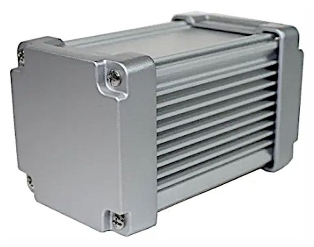
Figure 5: Container as heat sink
Optimization of the position of the electronic components
Electronic components dissipate heat when a current flows through them. The quantity of heat depends on the power and on circuit design. The optimal arrangement of the electronic component, on a circuit, should provide for excellent air circulation and intelligent placement of the parts, taking into consideration the specifications of the electrical circuit. The components, optimally arranged under the thermal profile, can dissipate their heat in the environment (see figure 6).
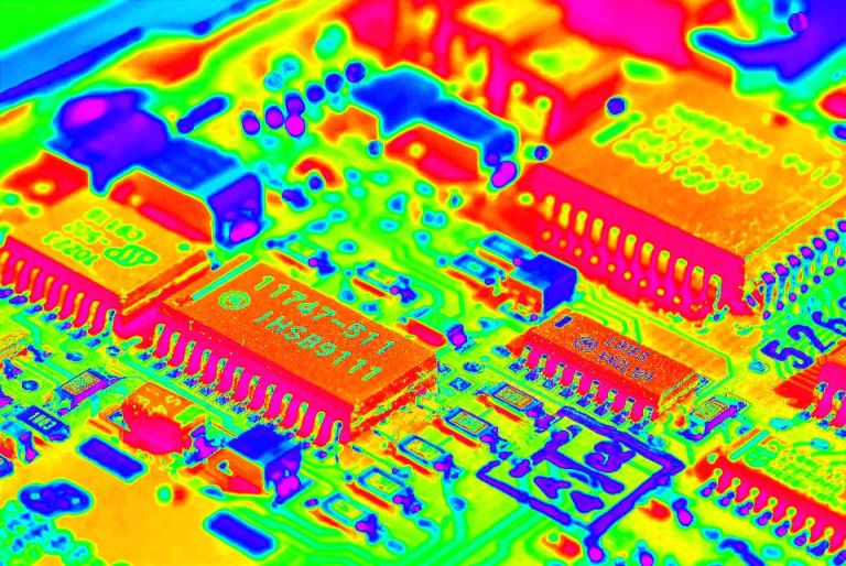
Figure 6: Heatmap of a circuit
The hottest components should be placed on a higher level than the cold ones. A circuit can have a metal cover over components mounted on a printed circuit board (PCB) with a thermal plane, to aid heat dissipation. Components contribute to generate heat and the resistance of the electrical connections, copper traces, and vias. Also, PCBs must be created with particular care. Designers have to study the dimensions of the components, size of the PCB and its material, layout, component placement and orientation with appropriate cooling methods. They can use an infrared (IR) camera to evaluate powered prototype boards, together with simulation software.
Active cooling
If it is not possible to apply passive solutions, it is best to use active solutions, which are normally made of a system for measuring the thermal parameters and an actuator (thermostat or hygrostat). It controls a device that changes the thermal quantities (fan, heater, air conditioner, etc). Active cooling methods, such as forced air or pumped liquid, can provide acceptable performances. However, this increases both energy consumption and noise. These systems provide forced convection through fans, air conditioning and air-air or air-water exchange.
Switching components with low RDS(on)
Modern switching circuits are made with silicon carbide (SiC) and Gallium nitride (GaN) MOSFETs (figure 7). These components offer great advantages, mostly from the thermal point of view and efficiency. Compared to silicon (Si), SiC has ten times the dielectric breakdown field strength, three (3) times the bandgap and three (3) times the thermal conductivity. The main features and benefits of SiC MOSFETs include:
- Very high temperature handling capability (max. TJ = 200 °C);
- Significantly reduced switching losses;
- Low on-state resistance (20 mOhm for 650 V devices and 80 mOhm for 1200 V devices);
- Very fast and robust intrinsic body diode.
GaN is also very useful to produce MOSFETs. GaN is a direct bandgap semiconductor. GaN based MOSFET and Metal Semiconductor Field Effect Transistors (MESFET) are useful for high power electronics, especially in electric cars and automotive applications.
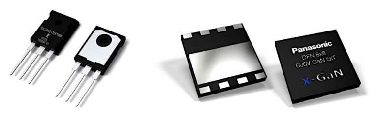
Figure 7: SiC and Gan MOSFETs
Conclusions
Designers should consider all the factors that influence temperature from the concept stage of the design. Thermal management techniques depend on the amount of heat the components and circuit dissipate, environment, design and enclosure. With the adoption of power microcircuits, it is imperative to manage energy without problems and dissipate heat to the maximum. The first factor influenced by a correct thermal management is, without a doubt, safety. Since most power devices are used in the automotive sector, prudence and safety are the main goals.
Good thermal management also helps to prevent overheating and circuit malfunctions. This leads to a drastic reduction in maintenance costs by power devices end users. They also improve energy efficiency and consumption. Better heat management leads to an increased performance in the system. Finally, a well-designed electronic circuit, with all the optimal thermal management criteria, preserves its electronic components making them last longer. For this reason, the maintenance of the whole system is also drastically reduced.