From data servers for the Internet of Things (IoT) to electric vehicles (EVs), designers of power systems remain under constant pressure to achieve higher power density and conversion efficiency. While much of the focus has been on semiconductor switching devices to achieve these improvements, the inherent characteristics of multi-layer ceramic capacitors (MLCCs) means they can also play an important role in helping designers meet their design requirements. These characteristics include low losses, high voltage and ripple current handling capabilities, high voltage withstand capability, and high stability over operating temperature extremes.
This article describes the construction of MLCCs and how ceramic capacitors boost power handling in DC and AC rails, while complementing fast switching semiconductors. It also sheds light on Class I and Class II dielectrics and how they allow miniature MLCCs to serve power systems such as snubbers and resonant converters.
How MLCCs are constructed
MLCCs are monolithic devices built from alternating layers of ceramic dielectric and metal electrodes (Figure 1). The laminated layers in MLCCs are constructed at high temperatures to produce a sintered and volumetrically efficient capacitance device. Next, a conductive termination barrier system is integrated on the exposed ends of the device to complete the connection.

Figure 1: Ceramic dielectrics are categorized according to temperature stability and dielectric constant. (Image source: KEMET)
Ceramics, the non-polar devices that offer greater volumetric efficiency, can deliver higher capacitance in smaller package sizes. Additionally, they are more reliable at high-frequency operations. This allows MLCCs to provide the right combination of dielectric, termination system, form factor, and screening.
Still, several issues call for due diligence on the part of designers when choosing ceramic capacitors for high power density applications. For a start, capacitance can be affected by the operating temperature, applied DC bias, and time after last heat. The time after last heat, for instance, can cause a shift in capacitance, which leads to capacitor aging (Figure 2).
|
Figure 2: The aging rates in capacitance percentage over time. (Image source: KEMET)
More importantly, the ripples generated by fast switching IGBT or MOSFET semiconductor devices can affect the performance because every capacitor has some impedance and self-inductance. So, it’s imperative that capacitors limit fluctuations as devices like inverters sporadically demand heavy currents, calling for a high ripple current tolerance.
Then there is the capacitor’s effective series resistance (ESR), a vital characteristic that represents the total internal resistance as specified at a given frequency and temperature. By minimizing the ESR, a designer reduces power loss due to heat generation.
Next, a low effective series inductance (ESL) increases the operating frequency range and allows further miniaturization of ceramic capacitors. Together, a low ESR and a low ESL boost a capacitor’s power-handling capability and minimize the device parasitics. Moreover, they contribute to lower losses, which in turn allow capacitors to operate at high ripple current levels.
Another critical design consideration is the choice of dielectric material. This determines the change in capacitance over temperature (Figure 3). While Class I dielectric materials such as C0G and U2J offer more temperature-stable dielectrics, they have a lower dielectric constant (K). On the other hand, Class II materials like X7R and X5R feature mid-range stability as well as K value while offering much higher capacitance values.
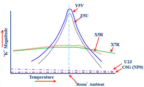
Figure 3: Class I and Class II dielectric materials mainly differ in terms of how much capacitance will change over a specific temperature. (Image source: KEMET)
However, for fast switching power systems, the higher the operating frequency, the lower the capacitance required to deliver power. This enables lower K ceramic capacitors to replace bulky high capacitance film capacitors, significantly enhancing the power density. These ceramic capacitors come in smaller footprints, so they can be mounted closer to fast switching semiconductors while requiring minimal cooling in high power density applications.
Class I dielectric MLCCs
KEMET’s KC-LINK capacitors such as the CKC33C224KCGACAUTO (0.22 microfarad (µF), 500 volt), the CKC33C224JCGACAUTO (0.22 µF, 500 volt), and the CKC18C153JDGACAUTO (15 nanofarad (nF), 1000 volt) are good examples of Class 1. They utilize Class 1 calcium zirconate dielectric material that facilitates extremely stable operation with no capacitance loss due to switching frequency, applied voltage, or ambient temperature. The low-loss calcium zirconate dielectric material also minimizes the aging effects because there is no capacitance shift over time.
The KC-LINK capacitors utilize C0G dielectric technology to achieve a very low ESR, and the ability to manage a very high ripple current which is necessary for high power density designs. The high mechanical robustness allows these Class I ceramic capacitors to be mounted without the use of lead frames, which also contributes to extremely low ESL.
These ceramic capacitors can operate at very high ripple currents with no change in capacitance versus DC voltage, and negligible change in capacitance versus an operating temperature range of -55°C to 150°C. They are available with capacitance values ranging from 4.7 nF to 220 nF, and voltage ratings spanning from 500 volts to 1,700 volts (Figure 4).
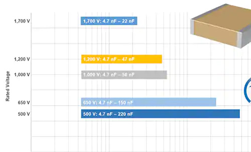
Figure 4: With an operating temperature of 150°C, KC-LINK ceramic capacitors can be placed closer to fast switching semiconductors in high power density applications that require minimal cooling. (Image source: KEMET)
Here, it’s worth noting that KC-LINK capacitors, which are based on Class 1 dielectric material, offer lower on-chip capacitance than equivalently-sized Class 2 capacitors. So, if more capacitance is needed, multiple KC-LINK capacitors can be bonded together into a single monolithic structure to create higher density packaging.
The outcome of this capacitor consolidation is a low-noise solution similar to KC-LINK but with up to 125 percent more capacitance. KEMET's KONNEKT surface mount capacitors, also based on a Class I dielectric material, provide higher capacitance values ranging from 100 picofarad (pF) to 0.47 µF. They retain over 99% of their nominal capacitance at rated voltages and are well suited for timing-critical and applications subject to temperature cycling and board flexure.
Stacking MLCCs for more capacitance
The KONNEKT ceramic capacitors, including the C1812C145J5JLC7805, the C1812C944J5JLC7800, and the C1812C944J5JLC7805, are created by vertically or horizontally stacking two to four ceramic capacitors while retaining the integrity of the device. The C1812C944J5JLC7800 ceramic capacitor offers a capacitance of 0.94 µF by stacking two devices, while the C1812C145J5JLC7805 ceramic capacitor takes the capacitance value to 1.4 µF with three devices stacked together.
These MLCCs utilize the transient liquid phase sintering (TLPS) material to bond component terminations together and thus create a leadless multi-chip solution. The leadless multi-chip solution makes the capacitor compatible with existing reflow processes. TLPS, a metal matrix composite bond made of copper-tin material, is used as a replacement for solder. It forms a metallurgical bond between two surfaces, in this case, the U2J layers.
The fact that capacitors can be integrated in both orientations minimizes the component footprint and maximizes the bulk capacitance of a stacked MLCC device (Figure 5), allowing KONNEKT ceramic capacitors to achieve the capacitance range previously possible only with Class II dielectric materials such as X5R and X7R.
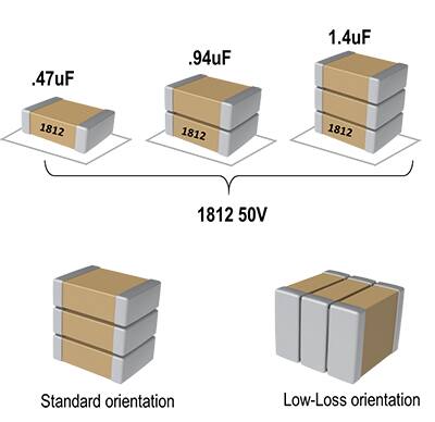
Figure 5: MLCCs can be stacked to increase capacitance and placed in a low-loss orientation to lower ESR and ESL. (Image source: KEMET)
In a low-loss orientation, less electrical energy is converted to heat, which in turn improves the energy efficiency and further enhances a capacitor’s power handling capabilities. The low-loss orientation also lowers both ESR and ESL and thus increases a ceramic capacitor’s ability to handle ripple currents.
The use of TLPS material, combined with an ultra-stable dielectric, enables ceramic capacitors to handle extremely high ripple currents in the hundreds of kilohertz range. For instance, with the C1812C145J5JLC7805 U2J 1.4 μF KONNEKT capacitor, the ESL is 1.6 nanohenry (nH) when mounted in standard orientation, but it reduces to 0.4 nH in low-loss orientation. Likewise, in low-loss orientation, the ESR is reduced from 1.3 milliohm (mΩ) to 0.35 mΩ, lowering system losses and limiting the temperature rise.
KEMET's U2J KONNEKT surface mount capacitors limit their capacitance change to –750 ±120 parts per million (ppm)/°C across temperatures ranging from –55°C to 125°C. This allows the U2J ceramic capacitor to exhibit a negligible shift in capacitance versus DC voltage, and a predictable linear change in capacitance with respect to ambient temperature.
AC line ceramic capacitors
The ceramic capacitors mentioned in the above sections stabilize and smoothen the voltage and current on DC rails and thus prevent decoupling spikes caused by fast switching. However, ceramic capacitors are also used in AC line filtering, AC/DC converters, and power factor correction (PFC) circuits.
Here, it’s important to note that AC line ceramic capacitors come in both safety and non-safety rated formats. While the safety rated capacitors suppress electrical noise and protect designs from overvoltages and transients, higher capacitance/voltage (CV) levels are not available in these safety-certified MLCCs.
Non-safety rated AC ceramic capacitors, available in a variety of sizes and CV values, can be used for continuous use in AC line conditions. KEMET’s CAN series of ceramic capacitors are qualified for AC line conditions of 250 VAC at 50/60 Hz line frequencies and other non-safety applications.
Figure 6: The CAN series AC line capacitors offer low leakage current and low ESR at higher frequencies. (Image source: KEMET)
The AC line capacitors offer low leakage current and low ESR at high frequencies (Figure 6). They cater to both line-to-line (Class X) and line-to-ground (Class Y) applications, and they meet the impulse criteria outlined in the IEC 60384 standard.
The CAN series of ceramic capacitors are available in both X7R and C0G dielectrics. The C0G dielectric, as shown in the case of DC link capacitors, exhibits no change in capacitance with respect to time and voltage, and it shows only a negligible change in capacitance regarding ambient temperature. On the other hand, in ceramic capacitors such as the CAN12X153KARAC7800 and the CAN12X223KARAC7800, X7R exhibits a predictable change in capacitance regarding time and voltage, and features a minimal change in capacitance due to ambient temperature.
The CAN12X153KARAC7800 ceramic capacitor offers a capacitance value of 0.015 µF, while the CAN12X223KARAC7800 device features a 0.022 µF capacitance. Both of these MLCC devices offer a 10% tolerance.
Conclusion
As power delivery systems continue to shrink and pack more power into smaller form factors, MLCCs are playing a crucial role in designs ranging from server power supplies to wireless chargers to power inverters. They smoothen DC and AC voltage, stabilize current ripples, and ensure thermal management in power designs seeking to improve conversion efficiency. As shown here, the choice of Class I and Class II dielectrics provides MLCCs with leverage to tailor capacitance and other critical parameters like ESR and ESL according to specific application needs.